

Behind every residential thermostat is a thin cable with a handful of colored wires. Each one carries a simple message from the thermostat to the equipment: run the fan, start cooling, start heating. The system runs on 24 volts and the logic is straightforward, yet thermostat wiring causes a steady stream of service calls, mostly after a homeowner or an inexperienced installer has changed a thermostat. Knowing what each terminal does makes those calls quick.
How the control circuit works
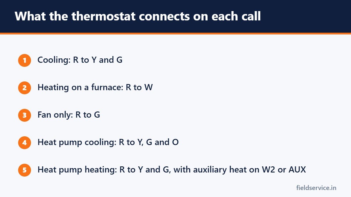
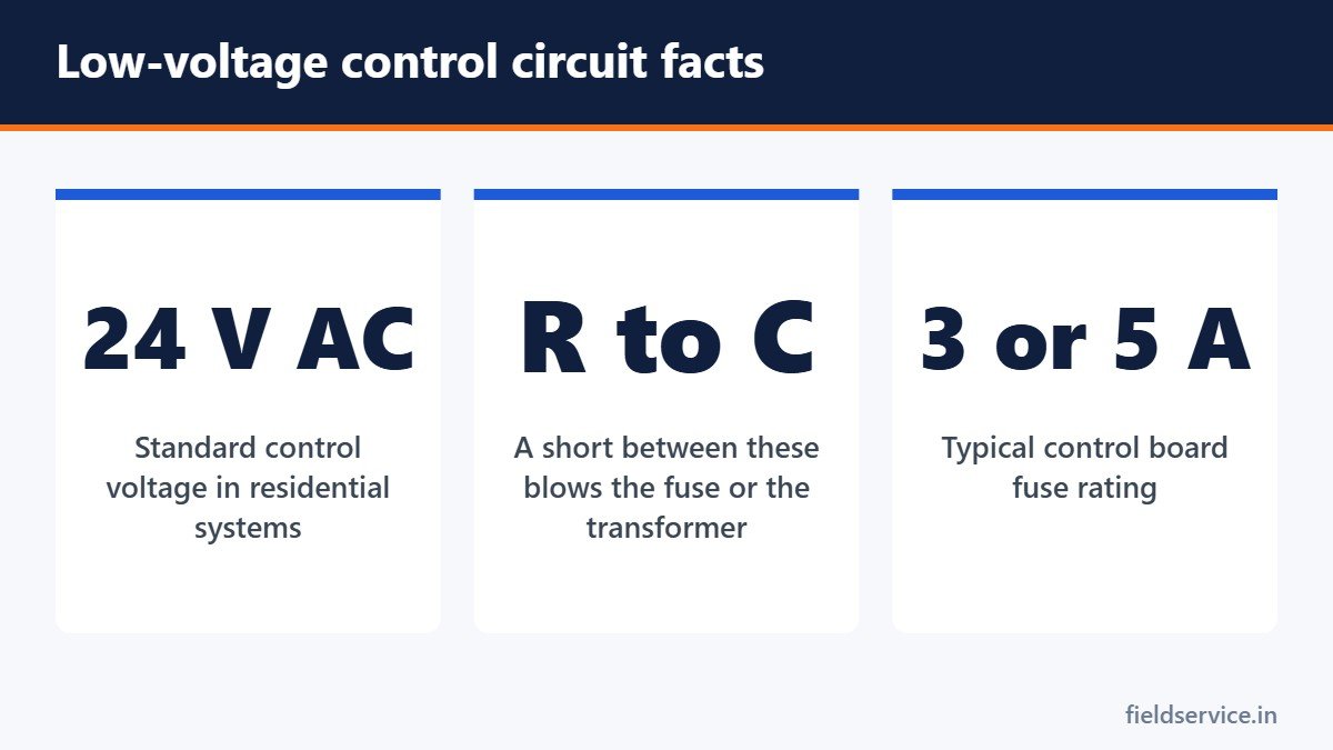
A transformer in the furnace or air handler steps the supply voltage down to 24 volts AC. One side of the transformer is R, the hot side. The other is C, the common. The thermostat is essentially a set of switches. When it calls for cooling, it connects R to Y. When it calls for heat, it connects R to W. Each connection sends 24 volts down a wire to energize a relay, a contactor or a control board input at the equipment.
| Terminal | Function | Usual wire color |
|---|---|---|
| R (Rc, Rh) | 24-volt power from the transformer | Red |
| C | Common: the return path to the transformer | Blue or black |
| W (W1) | First-stage heat | White |
| W2 | Second-stage or auxiliary heat | Varies |
| Y (Y1) | First-stage cooling: the compressor | Yellow |
| Y2 | Second-stage cooling | Varies |
| G | Indoor fan | Green |
| O/B | Heat pump reversing valve | Orange (O) or dark blue (B) |
The terminals in more detail
R, Rc and Rh
R is the 24-volt supply. Some thermostats have separate Rc and Rh terminals for systems where cooling and heating have separate transformers, such as a boiler with a separate air conditioner. With a single transformer, the two are joined by a jumper or an internal switch.
C, the common
C completes the circuit back to the transformer and gives the thermostat continuous power. Battery thermostats did not need it. Wi-Fi thermostats generally do. See smart thermostat installation.
W, heat
W calls for heat. On a furnace it starts the ignition sequence. On an air handler with electric heat it energizes the heat strips. W2 is a second stage.
Y, cooling
Y energizes the contactor in the outdoor unit, starting the compressor and the outdoor fan. On a heat pump, Y runs the compressor in both heating and cooling.
G, fan
G runs the indoor blower. In cooling, the thermostat energizes G with Y. In heating on a gas furnace, the furnace control normally runs the blower itself.
O/B, the reversing valve
On a heat pump, this terminal switches the reversing valve between heating and cooling. Most manufacturers energize the valve in cooling, using O. Some energize it in heating, using B. See heat pump basics.
Colors are a convention
The colors in the table are the usual practice, and nothing more. Nothing forces an installer to follow them, and in older homes and after repairs they often have not been followed. A blue wire may be the common, or it may be B on a heat pump, or it may be unused. Always identify a wire by the terminal it is connected to at both ends, and never by color alone.
Heat pump wiring
A typical heat pump uses R, C, Y, G and O or B, plus a terminal for auxiliary heat, labeled W2, AUX or E depending on the thermostat. Some thermostats have a separate E terminal for emergency heat. The thermostat must be configured as a heat pump with the correct reversing valve setting and the correct type of backup heat. A mistake in configuration produces the same symptoms as a mistake in wiring.
Other terminals you may see
- Y2 and W2 for two-stage equipment
- L for a fault or service indicator on some heat pumps
- S or T for outdoor or remote temperature sensors
- HUM, DEHUM and VENT for accessories
- Lettered or numbered data terminals on communicating systems, which use the manufacturer’s own protocol and are not interchangeable with conventional wiring
Before you touch the wires
- Turn off power to the indoor unit, and to the outdoor unit if it has a separate control circuit.
- Photograph the wiring at the thermostat and at the control board.
- Label each wire with the terminal it was on.
- Check how many conductors are in the cable and whether any are unused.
If R touches C with the power on, the short will blow the low-voltage fuse on the control board, usually a 3-amp or 5-amp automotive-style fuse. On equipment with no fuse, it can burn out the transformer.
Diagnosing with a meter
Set the meter to AC volts. See how to use a multimeter.
- R to C should read about 24 volts, commonly between 24 and 28. No voltage means a blown fuse, a failed transformer, an open safety switch such as a float switch in the R circuit, or no supply power.
- Y to C should read 24 volts during a call for cooling. If it does at the thermostat but not at the outdoor unit, the fault is in the cable or a safety device in between.
- W to C should read 24 volts during a call for heat.
- G to C should read 24 volts when the fan is called.
To separate a thermostat fault from an equipment fault, remove the thermostat and briefly join R to the terminal in question at the wall, with insulated tools. If the equipment responds, the thermostat or its configuration is the problem. If it does not, the fault is downstream.
Common problems
- Blown low-voltage fuse. A shorted wire, often where the cable passes through the cabinet or where it has been damaged outdoors. Find the short before replacing the fuse.
- Thermostat blank. No C wire, a blown fuse, a tripped float switch or dead batteries.
- Heat pump heats in cooling mode. O/B setting or wire.
- Fan will not stop. G shorted to R, a stuck relay, or the fan set to on.
- Outdoor unit does not start. Broken Y wire or common in the outdoor cable, often damaged by trimmers or animals.
- Loose connections at the terminal block or control board.
The cable
Thermostat cable is normally 18 AWG and sold by the number of conductors. Five conductors cover a basic single-stage system with a common. Heat pumps and multi-stage systems need more. When running new cable, install more conductors than you need today. The spare wires cost little and save a great deal later.
What this does not cover
Line-voltage thermostats, used on electric baseboard heat, switch 120 or 240 volts directly and are wired differently. Millivolt systems, found on some gas fireplaces and older wall furnaces, generate their own small voltage and need compatible controls. Communicating systems use the manufacturer’s own wiring and logic. Follow the equipment instructions for all three.
Related guides
- Condensate Drain Problems: Causes, Fixes and Prevention
- Wire Gauge and Ampacity Basics for Technicians
- MERV Ratings Explained: Choosing the Right Air Filter
Six everyday forms in Word and PDF, plus Excel workbooks that total mileage reimbursement and overtime pay.
Not sure yet? Try two forms free or see all packs.
Frequently asked questions
What does the C wire do on a thermostat?
It is the common side of the 24-volt transformer. It completes the circuit and gives the thermostat continuous power, which Wi-Fi thermostats generally need.
What color is the C wire?
Often blue or black, but colors are only a convention. Identify the wire by the terminal it is connected to at the thermostat and at the control board.
What happens if R touches C?
It short-circuits the transformer. On most equipment this blows the low-voltage fuse on the control board. On equipment without a fuse it can burn out the transformer.
What voltage should I read between R and C?
About 24 volts AC, commonly between 24 and 28 volts. No voltage points to a blown fuse, a failed transformer, an open safety switch or no supply power.
This article is an educational overview. Follow the thermostat and equipment manufacturers’ wiring diagrams.